Volumetric data is intrinsically difficult to visualise, especially on a 2D computer monitor. Various volume rendering techniques, including VR, exist, however for quantitative image inspection, where it is critical to access the gray value of individual voxels, extracting one 2-D slice of a volume is the method of choice. Thus, such volume slicing is implemented in almost all image analysis software packages. A conceptual challenge is that microscopes often produce anisotropic data, where the voxel spacing along the z-axis is typically larger than in the x and y axes. Thus, creating a slice, e.g., in the zy plane needs to be done with special care.
Prerequisites
Before starting this lesson, you should be familiar with:
After completing this lesson, learners should be able to:
Create slice views of volumetric image data
Master different ways of dealing with anisotropic voxels
Concept map
graph TD
V["Volume data"] --> S("Slicing")
V --- A["Anisotropic"]
S --> M["2D image"]
M -.- A
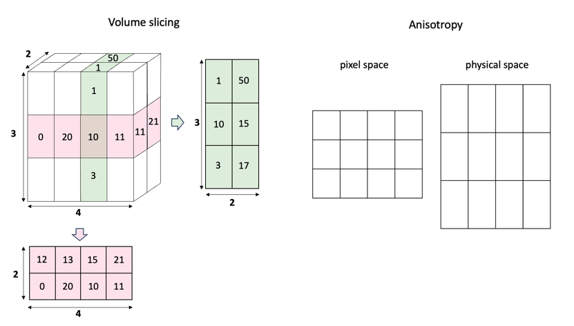
Figure
Volume slicing: Extracting 2-D slices from a 3-D volume, e.g. to be visualised on a computer monitor. Anisotropy: The measured data points have a different spacing in pixel vs. physical space, which poses a practical challenge for the rendering.
The word ‘slice’ is often used in different ways. The different ‘layers’ in the z-dimension are referred to as z-slices. Slicing (or subsetting) image data means that part of the image data is selected and ‘sliced out’ to form a new image. This can include selecting one or more dimensions, or just part of a dimension, for example selecting slice 6-12 of the Z-dimension. You can also rotate the data in one of the spatial dimensions and resample the data set to see that data from a different angle, which is sometimes referred to as ‘reslicing’.
Create slice views of the 3D volume in XY, XZ, and YZ planes
Appreciate and deal with anisotropic voxels sizes
Optionally also create slice views at non-orthogonal planes
Show activity for:
ImageJ GUI
Open a 3D image
Use Image > Properties to check for anisotropic voxel sizes
Use Image > Stacks > Orthogonal views to view the data in XY, XZ and YZ planes
Understand how the anisotropy is dealt with
Use Image > Stacks > Reslice to resample the data, exploring the below options for dealing with anisotropy
Output spacing
[ ] avoid interpolation, if this is checked, Output spacing is ignored
Use the line tool to draw a line ROI and again use Image > Stacks > Reslice to resample along this line
Slice the data at arbitrary angles using Plugins > BigDataViewer > Open Current Image]
Shift-X/Y/Z: slice along x,y,z.
Left button drag: slice along arbitray plane
I: toggle interpolation
ImageJ Macro
// open volumetric imageopen("https://github.com/NEUBIAS/training-resources/raw/master/image_data/xyz_16bit_calibrated__dna_metaphase.tif");// explore the dimensionswidth=getWidth();height=getHeight();depth=nSlices();print("Original Image Dimensions: Width = "+width+", Height = "+height+", Depth = "+depth);// reslice YZ with interpolationrun("Reslice [/]...","output=0.300 start=Left flip rotate");rename("YZ view");width=getWidth();height=getHeight();depth=nSlices();print("Image Dimensions YZ view: Width = "+width+", Height = "+height+", Depth = "+depth);// reslice XZ with interpolationselectImage("xyz_16bit_calibrated__dna_metaphase.tif");run("Reslice [/]...","output=0.300 start=Top");rename("XZ view");width=getWidth();height=getHeight();depth=nSlices();print("Image Dimensions XZ view: Width = "+width+", Height = "+height+", Depth = "+depth);// reslice YZ without interpolationselectImage("xyz_16bit_calibrated__dna_metaphase.tif");run("Reslice [/]...","output=0.300 start=Left flip rotate avoid");rename("YZ view");width=getWidth();height=getHeight();depth=nSlices();print("Image Dimensions YZ view WITHOUT interpolation: Width = "+width+", Height = "+height+", Depth = "+depth);// reslice XZ with interpolationselectImage("xyz_16bit_calibrated__dna_metaphase.tif");run("Reslice [/]...","output=0.300 start=Top avoid");rename("XZ view");width=getWidth();height=getHeight();depth=nSlices();print("Image Dimensions XZ view WITHOUT interpolation: Width = "+width+", Height = "+height+", Depth = "+depth);run("Tile")
Python Napari
# !First start Napari and drag and drop the image (https://github.com/NEUBIAS/training-resources/raw/master/image_data/xyz_16bit_calibrated__dna_metaphase.tif) in the Napari viewer.
# TODO: Fix it!
# Access the 3D array in the image layer
image=viewer.layers[0].data# assuming the image is in the first layer
shape=image.shapeprint("Image shape:",shape)# Compare the non-scaled image to the scaled image. You can also use the 3D view to better appreciate the dimensions.
voxel_dims=(0.300,0.1377745,0.1377745)# original voxel dimensions in µm, in order ZYX
scale_factor=1/voxel_dims[0]scaled_voxel_dims=[voxel_dims[0]*scale_factor,voxel_dims[1]*scale_factor,voxel_dims[2]*scale_factor]# rescaling the voxel dimensions to maintain proportions but display with a z-step of 1.
print("New voxel dimensions scaled relative to original",scaled_voxel_dims)viewer.add_image(d,name="Scaled to physical world dimensions",scale=scaled_voxel_dims)# Note that the scaled image layer contains the exact same data as the non-scaled image, but is only visualized differently to show the correct proportions.
# Create 2D slices (YX, ZX, and ZY)
mid_z_slice_ind=int(shape[0]/2)mid_y_slice_ind=int(shape[1]/2)mid_x_slice_ind=int(shape[2]/2)viewer.add_image(d[mid_z_slice_ind],name=f"z={mid_z_slice_ind}")viewer.add_image(d[mid_z_slice_ind],name=f"scaled: z={mid_z_slice_ind}",scale=scaled_voxel_dims[1:])viewer.add_image(d[:,mid_y_slice_ind,:],name=f"y={mid_y_slice_ind}")viewer.add_image(d[:,mid_y_slice_ind,:],name=f"scaled: y={mid_y_slice_ind}",scale=[scaled_voxel_dims[0],scaled_voxel_dims[2]])viewer.add_image(d[:,:,mid_x_slice_ind],name=f"x={mid_x_slice_ind}")viewer.add_image(d[:,:,mid_x_slice_ind],name=f"scaled: x={mid_x_slice_ind}",scale=scaled_voxel_dims[:2])# View in grid mode side by side
viewer.grid.stride=1viewer.grid.shape=(-1,2)viewer.grid.enabled=True
Assessment
Fill in the blanks
A set of 2D ____ placed on top of each other form a 3D ____.
An ____ voxel size can cause the image to appear ____ when viewing it at an angle.
Rendering anisotropic voxels can be done in various ways, such as ____, ____, or ____.
Solution
2D slices placed on top of each other from a 3D stack.
An anisotropic voxel size can cause the image to appear deformed when viewing at a certain angle.
One can render anisotropic voxels, by (i) isotropic resampling, (ii) just showing them as a square anyway, (iii) showing them as a rectangle.
True or False
Isotropic image data has voxels of equal XYZ dimensions.
Slicing is the process of sectioning the data, that has more than two dimensions, along defined axes and dimensions.
Reslicing is a term used to indicate repeated slicing.
Solution
True
True
False - Typically, the term reslicing refers to resampling volumetric data from a different direction, such that the resulting image stack is a rotated version of the original stack.