Spherical aberrations
Spherical aberrations create blurry and low contrast images. The aberrations are dynamic and are often introduced by the sample itself (cover glass thicknes, refractive index mismatch in immersion/mounting/sample media, depth of the sample …).
It is important to understand the effect of spherical aberrations to:
- correctly interpret the imaging results,
- adapt the experimental protocol
Prerequisites
Before starting this lesson, you should be familiar with:
Learning Objectives
After completing this lesson, learners should be able to:
Intensity Loss (Dimming): Understand why light fails to converge at a single focal point, leading to a dimmer and less contrasty signal
Learn how the difference between your immersion oil and your sample environment triggers these aberrations.
Z-Shift and Scaling: Identify why objects appear at the wrong depth or seem elongated/shortened in 3D space.
Concept map
Mismatch"] CG["Wrong Coverglass
Thickness"] SD["Imaging Deep
into Tissue"] end %% 2. The Physical Mechanism Phys["Non-coincident focal points:
Marginal rays vs. Central rays"] %% 3. Image Artifacts subgraph Artefacts [Image Artefacts] Asym["Asymmetric PSF
(Z-Smearing)"] Loss["Intensity Drop
(Dimmer Signal)"] ZErr["Axial Scaling Error
(Depth Distortion)"] end %% 4. Solutions subgraph Solutions [How to Fix] Coll["Correction Collar
Adjustment"] Mount["RI Matching
(Mounting Media)"] Water["Matching Immersion
Objectives"] end %% Logical Flow Causes --> Phys Phys --> Artefacts Artefacts -.-> Solutions %% Styling for 10.7.0 classDef cause fill:#f1f1ff,stroke:#0984e3,stroke-width:2px; classDef phys fill:#fff7e6,stroke:#ffa502,stroke-width:2px; classDef art fill:#fff1f1,stroke:#d63031,stroke-width:1px,stroke-dasharray: 5 5; classDef sol fill:#f1fff1,stroke:#27ae60,stroke-width:2px; class RI,CG,SD cause; class Phys phys; class Asym,Loss,ZErr art; class Coll,Mount,Water sol;
Figure
Activities
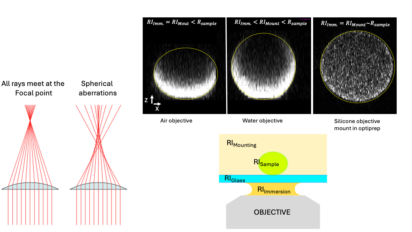
Compare images acquired with different objectives and mounting
Open the image xyz_16bit__oocyte_mRNA_pbs. The image shows mRNA labelled in a clytia hemispherica oocyte mounted in water and imaged with a water objective.
- Inspect how the intensity changes when moving through the Z-stack.
- Inspect how the cortical (outer boundary of the cells) intensity seems brighter than inside the cell.
- Why do we observe a lower intensity in the middle of the cell?
Open the image xyz_16bit__oocyte_mRNA_optiprep. The sample is mounted in a medium with higher refractive index than water and imaged with a silicon objective. Inspect how the now the intensity distribution is different. Now the mRNA (small dots) seems to be distributed more evenly through the sample.
- Inspect how the intensity changes when moving through the Z-stack.
- Inspect how the cortical (outer boundary of the cells) intensity seems brighter than inside the cell.
- Why do we observe a higher intensity in the middle of the cell compared to the PBS case?
Show activity for:
ImageJ GUI
Open the image xyz_16bit__oocyte_mRNA_pbs.
- Move along the Z dimension
- Plot a line profile along the diameter of the oocyte at Z ~ the middle of the oocyte [Analyze › Plot Profile], use a line thicknes > 10
- Create orthogonal views [Image › Stacks › Orthogonal Views] and appreciate how the fluorescene decays in Z and how it is lower in the middle
Open the image xyz_16bit__oocyte_mRNA_optiprep.
- Move along the Z dimension
- Plot a line profile along the diameter of the oocyte at Z ~ the middle of the oocyte [Analyze › Plot Profile], use a line thicknes > 10
- Create orthogonal views [Image › Stacks › Orthogonal Views]. How does it differ from the previous example
Assessment
Intensity and refractive index matching
You compare two images of a sample deep within a tissue block. Image 1 (mounted in a high-RI clearing agent and using an oil objective) appears significantly brighter than Image 2 (mounted in PBS and using a water objectvive), despite using identical laser power and gain settings. Why does the RI-matched sample appear brighter?
- Clearing agents physically move the sample closer to the lens.
- PBS causes rapid fluorescence quenching.
- Better RI matching ensures light rays converge at a tighter focal point rather than smearing axially.
- The clearing agent increases the light-gathering capacity (NA) of the objective.
Solution
Correct Answer: 3., When spherical aberration is reduced, the Point Spread Function (PSF) is tighter, concentrating the same number of photons into a smaller volume, which increases the peak intensity.
Apparent vs. Physical Depth
When imaging through a medium with a lower refractive index than the objective’s immersion medium (e.g., imaging into water with an oil objective), how does the apparent depth of a structure compare to its real physical depth?
A. The structure appears at its exact physical depth
B. The structure appears deeper than it actually is (Axial Scaling Error)
C. The structure appears shallower than it actually is
D. The structure appears wider in XY but its Z position remains accurate
Solution
Correct Answer: C, Refractive index mismatch causes light rays to bend, creating a “focal shift” that leads to axial scaling errors where structures appear at a different depth in the Z-stack than in physical reality.
Follow-up material
Recommended follow-up modules:
Learn more: