The Field of View (FOV) of a digital microscope is determined by the objective magnification, the intermediate magnification (e.g., camera adapter), and the physical dimensions of the detector sensor.
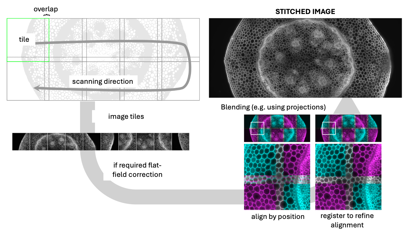
In cases where the structure of interest exceeds the FOV, we use tiled acquisition. This involves recording a grid of neighboring images—called tiles—with a specific percentage of overlap. In post-processing, these tiles are aligned and merged using stitching algorithms to reconstruct a single large-scale image.
Prerequisites
Before starting this lesson, you should be familiar with:
After completing this lesson, learners should be able to:
Learn how to stitch tiled images into a single large image
Learn which parameters affect the quality of the results
Concept map
graph LR
%% Define Inputs
subgraph Imaging [Imaging]
direction LR
LargeObject(Large object)
Tile1(Tile 1)
Tile_dot(...)
TileN(Tile N)
end
subgraph Input_Data [Input Data]
direction TB
B( )
style B fill:none,stroke:none,width:0px,height:0px
RawImages(Image Tiles)
StageCoords(Grid Positions)
Overlap(Overlap)
end
%% Define the Core Process
subgraph Stitching_Core [Stitching Algorithm]
direction TB
C( )
style C fill:none,stroke:none,width:0px,height:0px
Align(Step 1: Alignment)
Register(Step 2: Registration)
Blend(Step 3: Blending/Merging)
end
%% Define the Final Output
LargeImage(Final Large Stitched Image)
%% Define Connections/Flow
LargeObject-->Tile1
LargeObject-->Tile_dot
LargeObject-->TileN
Tile1 --- B
Tile_dot --- B
TileN --- B
B --- RawImages
RawImages --- C
StageCoords --- C
Overlap --- C
C --> Align
Align --> Register
Register-->Blend
Blend --> LargeImage
%% Styling for clarity (Optional but helpful)
classDef process fill:#f9f,stroke:#333,stroke-width:2px;
classDef input fill:#ccf,stroke:#333,stroke-width:1px;
classDef output fill:#cfc,stroke:#333,stroke-width:2px,stroke-dasharray: 5 5;
class Align,Blend,Register process;
class RawImages,StageCoords,Overlap input;
class LargeImage output;
Download the compressed image tiles xyc_16bit__hoechst_phalloidin_tiles.zip. The images are ordered in a regular pattern left-right, top-down (snake), we will estimate the overlap by trial and error (simulating the case where some metadata is lost). Starting with the correct value of overlap is important to get the best optimal alignment. Stitching errors are better observed when the fusion method uses a maximum or minimum.
Perform a stitching by using an overlap of 5%, 10%, and 15%, use maximum blending option. Do not compute the overlap.
Inspect the images, inp particular at the overlap between tiles, and notice that some of the overlaps gives better, but not perfect, results
Perform a stitching using the optimal overlap and allow for compute overlap. This will optimize the overlap for every tile pair
Try different options for the blending of the tiles
Start the stitching plugin [Plugins › Stitching › Grid/Collection stitching]
Set Type to Grid: snake by rows and Order to Right & Down
We have 4 tiles set Grid size x: and Grid size y to 2
Set the § Tile overlap [%] to 10
Set First file index to 1
Set the directory where the zip file has been unpacked
Set names for tiles to xyc_16bit__hoechst_phalloidin_tile_{ii}.tif
Set Fusion method to *Linear Blending
Check [x] Compute overlap ..
Press OK
Assessment
Why is it standard practice to include an overlap (typically 10-20%) between adjacent tiles during acquisition?
To increase the overall magnification of the final mosaic
To provide redundant information used by registration algorithms to calculate the exact alignment
To compensate for the low light sensitivity of the detector
To ensure that the file size of each tile remains constant
Solution
2 Registration algorithms (like phase correlation or feature matching) require a shared region to identify corresponding
Illumination Artifacts If individual tiles exhibit “vignetting” (darker edges) and are stitched together without prior correction, what is the most likely result in the final large image?
The image will appear perfectly seamless.
The resolution of the image will decrease by 50%.
A visible “checkerboard” pattern or grid-like intensity variations will appear across the mosaic.
The colors in the center of the image will shift toward the red spectrum.
Solution
3 Uneven illumination causes “shading” at the tile borders. To avoid this, flat-field correction must be applied to each tile before the stitching process to ensure intensity homogeneity.